
EN 61000-4-3, “Electromagnetic compatibility (EMC) – Part 4-3: Testing and measurement techniques – Radiated, radio-frequency, electromagnetic field immunity test”, defines how to test the resistance of equipment to radio transmissions arriving through the air. Laboratories call it “radiated immunity” or the “RF field test”; it is the test in EMC testing that needs the most equipment, because it requires an anechoic chamber.
Let us take care of EN 61000-4-3 testing and the CE marking of your product together; CE Danışmanı (CE Consultant) manages the whole process.
What does this test simulate?
Mobile phones, two-way radios, Wi-Fi access points, base stations and broadcast transmitters fill the environment with radio waves. These waves induce small voltages in the cables and circuit traces of equipment; a sensitive measuring circuit may show a wrong value, a sensor may misread, a controller may freeze. The test places the equipment in a field of known strength in the laboratory and shows whether it keeps working.
To imitate real transmissions the field is applied with 80 % amplitude modulation by a 1 kHz sine wave, so the effect of interference demodulated at audio frequencies is seen as well.
EN 61000-4-3 at a glance
| Current edition | IEC 61000-4-3:2020 (4th edition, replacing the 2006 edition with A1:2007 and A2:2010); applied in Europe as EN IEC 61000-4-3:2020 |
|---|---|
| Official title | Electromagnetic compatibility (EMC) – Part 4-3: Testing and measurement techniques – Radiated, radio-frequency, electromagnetic field immunity test |
| Type of standard | Basic EMC test standard: defines the test method; the level, the frequency range and the performance criterion are set by product and generic standards |
| Legislation | EMC Directive 2014/30/EU; harmonised product and generic standards refer to this test |
Which products does it apply to?
Almost every product containing electronic circuits; as an enclosure port test it also covers battery-powered equipment without a mains connection or cables.
- Household appliances, multimedia equipment (EN 55035), lighting, measuring and control equipment, industrial automation, medical devices.
- The generic standards require 3 V/m in residential environments and 10 V/m in industrial environments; product standards may choose other levels and frequency bands.
- For products containing a radio transmitter the test is planned together with the EMC standards of the radio equipment legislation (ETSI EN 301 489).
Test setup
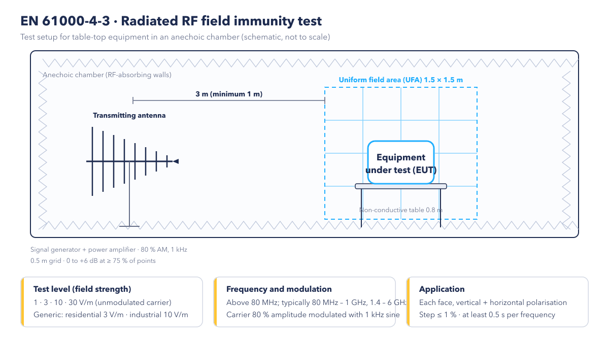
- Chamber: the test is carried out in an anechoic chamber whose walls are lined with RF-absorbing material, so that the field comes only from the antenna and is not reflected by the walls.
- Uniform field area: a 1.5 × 1.5 m area (minimum 0.5 × 0.5 m) in the plane where the equipment will stand is verified beforehand: at no fewer than 75 % of the grid points spaced 0.5 m apart, the field strength must lie between 0 and +6 dB of the target. This verification is done without the equipment, at least once a year.
- Antenna: the distance between the transmitting antenna and the field area is preferably 3 m, at least 1 m. The signal generator and the power amplifier stay outside the chamber.
- Equipment: table-top equipment stands on a 0.8 m non-conductive table, floor-standing equipment on an insulating support of at least 0.05 m; one face coincides with the field area. Cables are arranged as in a typical installation.
- Sweep: the frequency is swept in steps of at most 1 % of the previous frequency; at each frequency the test pauses long enough for the equipment to respond, never less than 0.5 s.
- Faces and polarisation: the four faces of the equipment are turned towards the antenna in turn; each face is tested twice, with vertical and horizontal polarisation.
Test levels
| Level | Field strength (unmodulated carrier) |
|---|---|
| 1 | 1 V/m |
| 2 | 3 V/m |
| 3 | 10 V/m |
| 4 | 30 V/m |
| X | special level set by the product standard |
The standard covers frequencies above 80 MHz; the generic standards require the ranges 80 MHz – 1 GHz and 1.4 – 6 GHz. 3 V/m is typical for residential and light-industrial environments and 10 V/m for industrial environments; your product standard sets the exact level.
Performance criteria
- A: the equipment works normally within its specified limits while the field is applied. As this is a continuous phenomenon, the generic standards require this criterion.
- B: temporary degradation that recovers by itself.
- C: temporary loss of function that needs user action or a restart.
- D: damage to hardware or software, or loss of data. The test is failed.
For equipment making analogue measurements, “normal operation” is defined with the tolerance stated by the manufacturer in the test plan; this definition goes into the report and must not conflict with the Low Voltage Directive safety evaluation.
Place in the CE marking process
- The EMC standard of the product is identified; the field strength, the frequency bands and the performance criterion are read from it.
- Cable screens, housing openings and filters on analogue inputs are reviewed during design; a pre-test with a near-field probe is run if needed.
- The test is carried out in an accredited laboratory’s anechoic chamber; the report records the faces, polarisations and monitored functions.
- The report goes into the technical file; the EU Declaration of Conformity under the EMC Directive is drawn up and the product is CE marked.
Standards applied together
- EN 61000-4-6: conducted RF immunity (below 80 MHz, through cables)
- EN 61000-4-2: electrostatic discharge (ESD) immunity
- EN 61000-4-8: power-frequency magnetic field immunity
- EN 61000-6-1 and EN 61000-6-2: generic immunity for residential and industrial environments
Frequently asked questions
What is the difference between radiated and conducted RF immunity?
Both imitate the effect of radio transmitters. Above 80 MHz the wavelength is short and interference enters the housing and short cables through the air, so a field is applied with an antenna. Below 80 MHz the wavelength is long and interference enters through long cables, so EN 61000-4-6 injects the signal directly onto the cable.
Why is the test expensive and slow?
The anechoic chamber, the power amplifier and the field probe are costly equipment, and each face is swept with two polarisations, in 1 % steps, pausing at least half a second per step, so a single product can take hours. The test time grows with the number of functions to monitor and the frequency range.
What if my product fails?
The path by which the interference enters is usually closed: cable screens are bonded to the chassis over 360°, housing openings are reduced or closed with conductive gaskets, RF filters are added to analogue inputs, and measured values are filtered sensibly in the firmware. Because the report states at which frequency and on which face the failure occurred, the fix is targeted.
Other standards in this group
- EN 61000-4-11: Voltage Dips and Interruptions Test
- EN 61000-4-2: Electrostatic Discharge Immunity Test
- EN 61000-4-4: Electrical Fast Transient Burst Test
- EN 61000-4-5: Surge Immunity Test

