
EN 61000-4-6, “Electromagnetic compatibility (EMC) – Part 4-6: Testing and measurement techniques – Immunity to conducted disturbances, induced by radio-frequency fields”, defines how to test the resistance of equipment to radio-frequency interference arriving through its cables. Laboratories call it “conducted immunity” or the “CDN test”; in EMC testing it complements the radiated RF test below 80 MHz.
Let us take care of EN 61000-4-6 testing and the CE marking of your product together; CE Danışmanı (CE Consultant) manages the whole process.
What does this test simulate?
Below 80 MHz the wavelength of a radio transmitter’s field is long, so it acts on the cables of the equipment rather than on the equipment itself: the power cable, a sensor line and a data cable behave like antennas and carry the interference inside. The test imitates this by injecting the radio-frequency signal directly onto the cable through a coupling network and checks whether the equipment keeps working.
To imitate real transmissions the signal is applied with 80 % amplitude modulation by a 1 kHz sine wave.
EN 61000-4-6 at a glance
| Current edition | IEC 61000-4-6:2023 (5th edition, replacing the 2013 edition); applied in Europe as EN IEC 61000-4-6:2023 |
|---|---|
| Official title | Electromagnetic compatibility (EMC) – Part 4-6: Testing and measurement techniques – Immunity to conducted disturbances, induced by radio-frequency fields |
| Type of standard | Basic EMC test standard: defines the test method; the level and the performance criterion are set by product and generic standards |
| Legislation | EMC Directive 2014/30/EU; harmonised product and generic standards refer to this test |
Which products does it apply to?
All electrical and electronic equipment with a mains cable, a DC supply cable, or signal and data cables leaving the product.
- The power port is tested on every product; signal and control ports are tested under the generic standards only where the cable may exceed 3 m.
- Battery-powered equipment without cables is not tested.
- The generic standards require 3 V in residential environments and 10 V in industrial environments; a product standard may choose another level.
Test setup
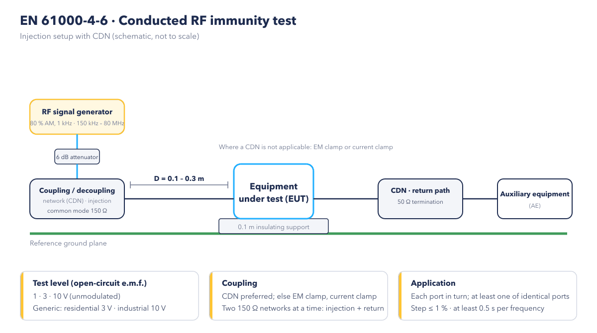
- Generator: the RF signal generator sweeps from 150 kHz to 80 MHz; a 6 dB attenuator sits at its output, and the level is set as the open-circuit voltage (e.m.f.) at the point where the equipment will be connected.
- Coupling network: the signal is injected onto the cable under test through a coupling/decoupling network (CDN). On the equipment side the CDN presents a common-mode impedance of 150 Ω to the reference ground; its decoupling section keeps the signal away from the mains or the auxiliary equipment.
- Return path: only two 150 Ω networks are used at a time: one for injection and one, terminated with 50 Ω, as the return path. Decoupling networks are fitted to the other cables.
- Equipment: the equipment stands on an insulating support 0.1 m above the reference ground plane; the coupling device is 0.1 to 0.3 m from the equipment and the cable is preferably shorter than 0.3 m.
- Clamp option: where a CDN cannot be fitted (for example because its attenuation disturbs the operation of the equipment), an EM clamp or a current clamp is used; direct injection is the last resort.
- Sweep: the frequency is swept in steps of at most 1 %; at each frequency the test pauses long enough for the equipment to respond, never less than 0.5 s. Frequencies known to be sensitive are tested in addition.
Test levels
| Level | Open-circuit voltage (e.m.f., unmodulated) |
|---|---|
| 1 | 1 V (120 dBµV) |
| 2 | 3 V (129.5 dBµV) |
| 3 | 10 V (140 dBµV) |
| X | special level set by the product standard |
The generic standard requires 3 V for residential and light-industrial environments and 10 V for industrial environments; the frequency range is 150 kHz – 80 MHz. Your product standard sets the exact level.
Performance criteria
- A: the equipment works normally within its specified limits while the signal is applied. As this is a continuous phenomenon, the generic standards require this criterion.
- B: temporary degradation that recovers by itself.
- C: temporary loss of function that needs user action or a restart.
- D: damage to hardware or software, or loss of data. The test is failed.
For inputs carrying analogue signals, “normal operation” is assessed with the tolerance defined by the manufacturer; this definition must not conflict with the Low Voltage Directive safety evaluation.
Place in the CE marking process
- The EMC standard of the product is identified; the level, the ports to be tested and the performance criterion are read from it.
- Cable screens, input filters and common-mode chokes are reviewed during design; a pre-test is run if needed.
- The test is carried out in an accredited laboratory; the report records the ports, the injection method and the monitored functions.
- The report goes into the technical file; the EU Declaration of Conformity under the EMC Directive is drawn up and the product is CE marked.
Standards applied together
- EN 61000-4-3: radiated RF field immunity (above 80 MHz)
- EN 61000-4-4: electrical fast transient (burst) immunity
- EN 61000-4-5: surge immunity
- EN 61000-6-1 and EN 61000-6-2: generic immunity for residential and industrial environments
Frequently asked questions
Why is the level given in volts rather than V/m?
The radiated test measures the strength of a field (V/m); the conducted test measures the open-circuit voltage of the signal injected onto the cable (V). Thanks to the standard 150 Ω coupling impedance, this voltage corresponds to a defined common-mode current in the cable and is repeatable between laboratories.
Which cables are tested?
The power cable always; signal, control and data cables according to the product standard, and under the generic standards those that may exceed 3 m. Where several identical ports exist, at least one is tested; bundles of cables running together for more than 10 m may be treated as one cable.
What if my product fails?
Usually a ferrite or common-mode choke is added at the cable entry, the cable screen is bonded to the chassis over 360°, RC or RF filters are placed on analogue inputs and the grounding layout of the board is improved. Because the report states on which port and at which frequency the failure occurred, the fix is targeted.
Other standards in this group
- EN 61000-4-4: Electrical Fast Transient Burst Test
- EN 61000-4-5: Surge Immunity Test
- EN 61000-4-11: Voltage Dips and Interruptions Test
- EN 61000-4-2: Electrostatic Discharge Immunity Test

